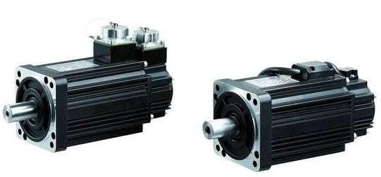
The editor has introduced the classification of servo motor encoders before. It can be seen that this device has many classifications and is widely used in various industries, but its principle is relatively complicated. So how should we understand servo motor inverters? Let’s learn together about the selection and system design of servo motor inverters! I hope it can increase everyone’s knowledge and broaden everyone’s horizons!
The selection of servo motor inverter is as follows:
Because the parameters of AC spindle motors are quite different from those of general induction motors, the rated current of AC spindle servo with the same power is larger than that of ordinary induction servo.
Therefore, when selecting a servo inverter, it is necessary to satisfy the servo rated current as the principle, otherwise it will not meet the requirements of the AC spindle servo. The operation mode of the servo inverter can achieve the following functions:
(1) Control the operation and stop of the servo inverter.
(2) Modify the frequency given value when operating the operating unit.
(3) Monitor the status of the servo inverter.
(4) Display servo inverter alarm and alarm history records. The operation of the servo inverter can be started and stopped by directly using the RuN and STOP keys on the operating unit. The status monitoring, alarm and alarm history record of the servo inverter can be directly controlled by using the buttons of the operating unit, and the corresponding status monitoring parameters (U1~U6) are displayed through operation.
In the operation mode, during the operation process of changing the frequency given value of the operating unit, the set frequency generally needs to be effective by pressing the data input key [ENTER]. However, for example, if the servo motor inverter parameter o2-05 is set to "1", Only after the input is completed can the input frequency take effect.
Servo motor inverter closed-loop system design:
As common configurations, servo motor inverters usually choose two-phase open collector input interface module PG-B2 and 2/3-phase line drive differential output interface module PG-X2; while CIMR-A1000 series servo inverters choose 2/3 Similar to the line-driven differential output interface module PG-X3.
The circuit design and connection requirements of the two modules are briefly described as follows:
The DC12V servo encoder can directly use the DC12V power supply provided by the interface module, but the load current cannot exceed 200mA. For other situations, the servo encoder should be powered by an external power supply. At this time, the 0V of the external power supply should be connected to the small end of the interface module. The connection terminals 1 to 4 of module TA2 are A and B two-phase pulse output terminals, and their driving capability is DC24/30mA. This signal can be used by other devices in the control system.
The PG-X2/X3 module can be connected to a 2-phase or 3-phase line drive pulse servo encoder with differential output. The input signal requirements of the module for the external servo encoder are as follows:
(1) Input signal: A/B two-phase or A/B/Z three-phase line driver differential input.
(2) Signal level: The high level without load is not greater than +6V; the low level with load is not less than ±2V.
(3) Input frequency: not greater than 300kHz.
(4) Signal driving capability: greater than DC5V/30mA.
The connection circuit between the PG-X2/X3 module and the servo motor encoder does not need to connect the TA1 connection end when the zero pulse is not used.


