Technical Knowledge
Home / News / Technical Knowledge / Analysis of vector control of permanent magnet synchronous motor
Last time we introduced the control method of the permanent magnet synchronous motor. It can be seen that there are three control methods of this motor. So what is the analysis of vector control of permanent magnet synchronous motor? Let’s discuss it together next!
With the development of high-function permanent magnet materials, power electronics technology, large-scale integrated circuits and computer technology, the application fields of permanent magnet synchronization (PMSM) are constantly expanding, and it has been widely used in high-precision control ranges such as CNC machine tools and robots. .
Because the requirements for motor control functions are getting higher and higher, the permanent magnet synchronous motor vector control system can achieve high precision, high dynamic functions, and a wide range of speed regulation or positioning control. The research on the permanent magnet synchronous vector control system has become a topic of small and medium-capacity AC One of the key points in servo system research, how to establish an effective simulation model has attracted more and more attention. Based on the analysis of the permanent magnet synchronization mathematical model, this paper uses the Simulink and Power System B1ock modules in the MATLAB language to establish a simulation model of the control system, and analyzes the simulation results as follows.
1. Mathematical model of permanent magnet synchronous motor
The mathematical model of permanent magnet synchronization is based on the following assumptions:
① Neglect the effects of saturation, eddy current, and hysteresis effects;
② The current of the motor is a symmetrical three-phase sine wave current;
③ The magnetomotive force of the permanent magnet is uncertain, that is, the equivalent excitation current is stable;
④ The three-phase stator windings are distributed in a symmetrical star shape in space, and the armature resistance and armature inductance of each stator winding are equal.
The permanent magnet synchronous motor is the primary link in the AC synchronous speed regulation system, and analyzing its mathematical model is particularly important to grasp its speed regulation characteristics. Take the axis of the fundamental wave excitation magnetic field of the rotor permanent magnet as the d axis. The q axis s the d axis 90 degrees along the direction of rotation. The dq axis rotates with the rotor at the angular speed ωr. Its spatial coordinates are between the d axis and the reference axis α. To show the TV point θr, the mathematical model of ideal permanent magnet synchronization in the dq rotating coordinate system can be written in the following form:
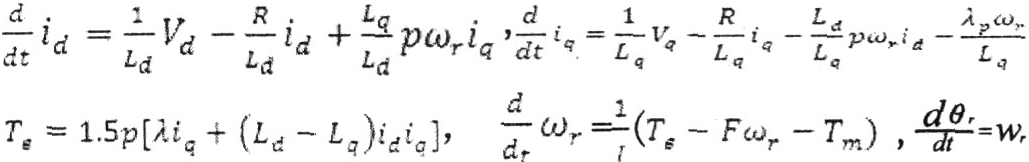
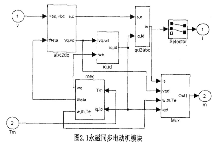
Based on the mathematical model, the permanent magnet synchronization module was established using Simulink, as shown in Figure 2.1:
2. Control principle of permanent magnet synchronous motor AC servo system
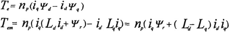
It can be seen from the above formula that the electromagnetic torque of permanent magnet synchronous fundamentally depends on the weight of the stator current on the q-axis. Because the permanent magnet synchronous rotor flux linkage is stable and stable, vector control oriented according to the rotor flux linkage is generally used. The essence of the control is to realize the torque control of the AC permanent magnet synchronous motor by controlling the stator current. When the rotational speed is below the base speed and the stator current is given, controlling id=0 can more effectively generate torque. At this time, the electromagnetic torque Tem=Pniqψr, it can be seen that the electromagnetic torque changes with the change of iq, This control method is the simplest. However, when the speed is above the base speed, because the excitation flux linkage of the magnet is constant, the electromotive force induced by the motor increases in proportion to the motor speed. The induced voltage of the motor also increases, but it is restricted by the upper voltage limit of the inverter connected to the motor end.
In actual control, the system detects the three-phase stator current flowing into the motor, so it is necessary to change the coordinates and change the current weight on the three-phase predetermined coordinates into the current weight on the rotor coordinate system through park and clarke. To complete the conversion from the stator coordinate system to the rotor coordinate system, it is necessary to detect the position of the motor rotor in real time during control. Commonly used rotor position detection sensors include incremental photoelectric encoders, positive photoelectric encoders and rotary transformers. The azimuth signal command is compared with the detected rotor azimuth. Through the adjustment of the azimuth controller, a speed command signal is output. The speed command signal is compared with the detected rotor speed signal. After being conditioned by the speed regulator, a current that controls the torque is output. Weight i*q, the current weight given signal is compared with the actual current weight of the motor through coordinate conversion, and is calculated by the current controller. Its output is converted by inverse park for calculation to generate PWM drive IGBT, which generates variable frequency and amplitude. The three-phase sinusoidal current is input into the motor stator to drive the motor to operate.
3. System simulation
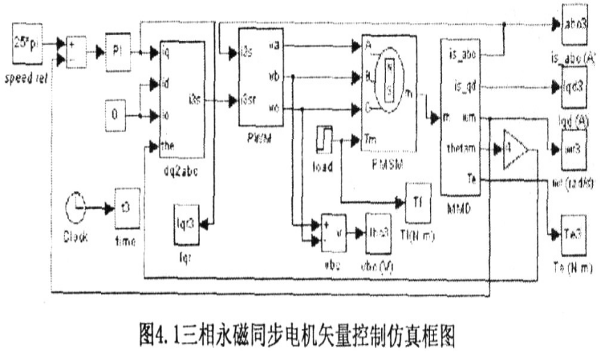
Figure 4.1 Three-phase permanent magnet synchronous motor vector control simulation block diagram The three-phase PMSM vector control system simulation block diagram based on rotor magnetic field orientation is shown in Figure 4.1. The PI module in the figure is a speed loop PI controller, which determines the current and torque weight based on the actual speed of the motor and the given speed; the PWM module uses current hysteresis control (as shown in Figure 4.2), so that the actual current of the motor changes with the given current, specifically The completion is as shown in Figure 4.3; the module dq2abc completes the 2r/3s conversion, and the detailed completion is as shown in Figure 4.4, in which the function modules Fcn, Fcnl and Fcn2 complete the 2r/3s conversion together; the MMD module is the motor measurement module, which measures the speed, current, and Signals such as rotor orientation: The PMSM module provides a permanent magnet synchronous motor model for MATLAB. Its specific implementation is shown in Figure 2.1.
4. Simulation graphics and result analysis
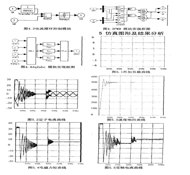
The motor parameters used in the simulation are as follows: the stator resistance is 2.875Ω, the stator direct-axis inductance and quadrature-axis inductance are both 8.5e-3H, the flux linkage between the permanent magnet poles and the stator winding is 0.175Wb, and the rotational inertia is 0.8e-3H. 3kgm2, pole pair number 6, given speed ωr=500rpm, at t=0.03s, the load torque suddenly changes from ON·m to 6N·m, see Figure (5.1).
It can be seen from the above simulation results that when an ordinary three-phase permanent magnet synchronous motor adopts a vector control scheme based on the orientation of the rotor magnetic field, and the speed outer loop adopts PI control, there will be a certain overshoot in the speed response process (see Figure (5.2)). When the load is suddenly added, the speed immediately drops, and then gradually returns to stability, as shown in Figure (5.3): If PID control is used in the speed outer loop, that is, a small differential link D is added to the speed outer loop and the proportional amplification coefficient P is appropriately reduced, it can be It can effectively reduce overshoot and shorten the time for the motor to reach steady state when starting the motor and suddenly adding load. The actual current of the quadrature axis always tracks the given current of the quadrature axis, as shown in Figure (5.5), and during the starting process and when the load is suddenly added, the two changes fluctuate greatly, while at steady state both are basically stable, and the electromagnetic torque is stable at steady state. Figure (5.4), in order to balance the external load; when the speed is stable, the three-phase stator current is a regular sinusoidal current, and the phases are sequentially different by about 120°.


Manager Guo:0575-83508980
Manager Zhou:0575-83508990

Phone:0575-83508993

Email: admin@jinyimotor.cn

Address: No. 8, Lishui Road, Sanwang Industrial Park, Huangze Town, Shengzhou City, Zhejiang Province, China
All rights reserved:Zhejiang jinyi motor Co.,Ltd.