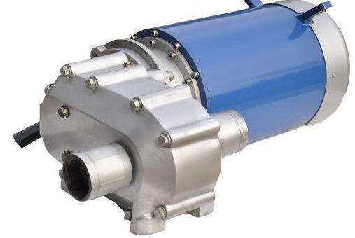
The permanent magnet brushless motor is a permanent magnet motor that is commutated or controlled by electronic circuits. The permanent magnet motor has two types: sine wave drive and square wave drive. This motor also has the characteristics of simple structure and reliable operation. So what is the specific structure of the permanent magnet brushless DC motor? Next, please read the detailed introduction below!
The permanent magnet brushless DC motor is mainly composed of three parts: the motor body, the orientation sensor and the electronic switch circuit.
The motor body is similar in structure to the permanent magnet synchronous motor, but does not have cage windings and other starting devices. The stator winding is generally made of multi-phase (for example: three-phase, four-phase, five-phase), and the rotor is composed of magnetic steel according to a certain number of pole pairs (2p=2, 4,...).
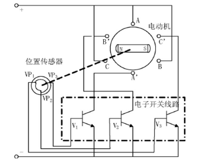
The motor body in the picture has three-phase north and south poles. The three-phase stator windings are separated and combined with the corresponding power switching equipment in the electronic switching circuit. The A-phase, B-phase, and C-phase windings are separated and connected with the power switching tubes 1V, 2V, and 3V. Connection, the tracking rotor of the position sensors 1VP, 2VP, and 3VP is combined with the motor shaft to detect the position of the motor rotor, and its output end is connected to the corresponding power switching device in the electronic switching circuit.
When a certain phase of the stator winding is energized, the current interacts with the magnetic field generated by the magnetic poles of the rotor magnet to generate torque, driving the rotor to rotate. The orientation sensor converts the orientation of the rotor magnet into an electrical signal to control the electronics. Switch lines, so that the stator windings are turned on in a certain order, and the stator phase current changes in a certain order as the rotor position changes. Because the conduction sequence of the electronic switch circuit is synchronized with the rotor angle, it plays the commutation effect of the mechanical commutator.
Therefore, the so-called brushless DC motor, in terms of its basic structure, can be considered as a motor system consisting of an electronic switch circuit, a permanent magnet synchronous motor and an orientation sensor.
The motor switch circuit is used to control the order and time of energization of each phase winding on the motor stator. It is mainly composed of two parts: a power logic switch unit and an orientation sensor signal processing unit. The power logic switch unit is the core of the control circuit. Its function is to distribute the power of the power supply to each winding on the stator of the brushless DC motor in a certain logical relationship, so that the motor can generate continuous torque. The order and time of each phase winding conduction mainly depends on the signal from the orientation sensor.


