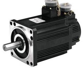
Last time we introduced the servo motor selection process, we can know that there are some things to pay attention to during the selection process. So what are the control methods of servo motors? Next, the editor will give a detailed introduction to this issue, hoping to help everyone!
The servo motor is a device that assists in motor acceleration, and the servo motor controls the speed and position very accurately. The servo motor is a motor controlled by a closed-loop controller. It has more encoder responses than ordinary motors. It can calculate the output target value based on the given and response, thereby controlling the movement speed and displacement of the motor.
General servo motor control methods include:
Servo motors are generally controlled by three loops. The so-called three loops are three closed-loop negative response PID conditioning systems. The PID loop inside is the current loop. This loop is completely carried out inside the servo driver. The output current of each phase of the driver to the motor is detected by the Hall device, and the negative reaction is used to set the current for PID conditioning, and then the output current is as close as possible to equal to Set the current and the current loop controls the motor torque, so in the torque mode, the driver's operation is small and the dynamic response is fast.
The second loop is the speed loop. The detected motor encoder signal is used for negative response PID conditioning. The PID output in the loop is directly the setting of the current loop, so the speed loop control includes the speed loop and the current loop. In other words, it is necessary to use the current loop in all modes. The current loop is the basis of control. While speed and position are controlled, the system is actually also controlling current (torque) to achieve corresponding control of speed and position.
The third loop is the position loop, which is the outer loop. It can be constructed between the driver and the motor encoder or between the external controller and the motor encoder or the final load, depending on the actual situation. Because the internal output of the position control loop is the setting of the speed loop, the system performs calculations on all three loops in the position control mode. At this time, the system has a large amount of calculations and the dynamic response speed is also slow.
1. Torque control: The torque control method is to set the external output torque of the motor shaft through the input of an external analog quantity or a direct address assignment. The specific performance is that, for example, if 10V corresponds to 5Nm, when the external analog quantity When set to 5V, the motor shaft output is 2.5Nm: If the motor shaft load is less than 2.5Nm, the motor rotates forward, when the external load is equal to 2.5Nm, the motor does not rotate, and when it is greater than 2.5Nm, the motor rotates (generally occurs under gravity load) ). The set torque can be changed by changing the analog setting in real time, or by changing the value of the corresponding address through communication. It is mainly used in winding and unwinding equipment that has strict requirements on the force of the material, such as wire-laying equipment or fiber-drawing equipment. The setting of the torque should be changed at any time according to the change of the surrounding radius to ensure the force of the material. Does not change as the surrounding radius changes.
2. Speed mode: The rolling speed can be controlled through analog input or pulse frequency. The speed mode can also perform positioning when there is an outer loop PID control of the upper control device, but it is necessary to transmit the position signal of the motor or directly The position signal of the load is given to the host for calculation purposes. The position mode also supports direct load outer ring detection of position signals. At this time, the encoder on the motor shaft end only detects the motor speed, and the position signal is provided by the direct detection device on the final load end. This has the advantage of reducing the load during the central transmission process. errors and increase the positioning accuracy of the entire system.
3. Position control: The position control mode generally determines the rolling speed through the frequency of externally input pulses and the rolling angle through the number of pulses. Some servo motors can also directly assign speed and displacement through communication methods. . Because position mode can strictly control both speed and position, it is generally used in positioning equipment.


