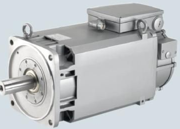
The servo motor system is an important link in electromechanical products. It can provide horizontal dynamic response and torque density. Therefore, the development trend of drive systems is to use AC servo drives to replace traditional hydraulic, DC, stepper and AC variable frequency speed drives. To take system performance to a whole new level, including shorter cycle times, higher productivity, better reliability and longer life. In order to achieve better functions of the servo motor, it is necessary to understand the precautions for the operation of the servo motor. The important thing is the adjustment method of the zero point of the servo motor. Let’s introduce it in detail below!
The adjustment method of servo motor zero point is as follows:
1. The encoder shaft rotates to find zero. When the encoder is installed, the rotating shaft corresponds to the zero position. Generally, this method is used for incremental values and single-turn values, and this method is also used for sleeve-type encoders. Its disadvantages are: the zero point is not easy to find and the accuracy is low.
2. It is equivalent to the above method, except that the encoder housing is rotated to find the change. This is mainly used for some compactly installed synchronous flange (also called servo flange) housings.
3. Turn on power to move the installation machine to zero. Turn on power and move the installed machine to the corresponding position of the corresponding encoder zero position for installation.
4. Offset calculation. Neither the machine nor the encoder needs to find change. The offset is obtained based on the error calculation between the encoder reading and the actual position. This offset is then subtracted from the encoder reading.
For example, the encoder reading is 100, but the actual position is 90. According to calculation, when the actual position is 0, the encoder reading should be 10, and this "10" is the offset. From now on, the number read by the encoder, Subtracting this offset is the position value. It can be repeated multiple times to modify the offset. For incremental encoders, the reading from the original mechanical zero position to Z point is used as the offset. Encoders with higher precision, or multi-turn encoders with larger ranges, often use this method.
5. Intelligent internal zero setting. Some encoders with intelligent functions can provide external setting functions, such as zero setting through the buttons on the encoder or external software setting functions.
6. What needs to be explained is that the zero position of the servo motor value encoder is the cyclic value of the encoding, whether it is a single-turn value or a multi-turn value. If it is set to zero, then it will go down (slide, move, inertia Overshoot, etc.), the data may jump suddenly. For high-digit values with many turns, the data may overflow the original setting range. In addition, the value encoder also has a problem with the rotation position. After zeroing, if the direction is wrong, it will jump from 0 to , and then from large to small. Although some imported encoders have an external zero setting function, it is recommended not to use this function.
7. The setting method is to preset a non-zero position (leaving a margin for slippage and overshoot) and preset the rotation direction offset calculation method. Another way is to set it to "center". The offset amount is the midpoint value. After the setting line is in positive contact with the power supply, the encoder output is the midpoint position. Such a stroke is /-half full. In such a stroke Within the range, regardless of the direction of rotation, it is guaranteed that the servo motor will not go through a zero point jump.


